COLLECTED BY
Organization:
Internet Archive
The Internet Archive discovers and captures web pages through many different web crawls.
At any given time several distinct crawls are running, some for months, and some every day or longer.
View the web archive through the
Wayback Machine.
Web wide crawl number 16
The seed list for
Wide00016 was made from the join of the top 1 million domains from CISCO
and the top 1 million domains from Alexa.
TIMESTAMPS
2HA5 single radio
On the top of this page, I must say you that this page is not practical.
I made some experimental projects about useing the valves with low voltage.
And I had a theme that " Challenge the lowest voltage of use of valve
! ". This project is one of my result of this theme. *** I have about
100 types of valves. 99% of them are picked up from the thrown away TV
set about 25 years ago by my younger brother. I examined a lowest voltage
of his plate able to make plate current with many types of valves. The
result was that 2HA5 was the champion. ( 2HA5 will be Japanese original
tube.) The grid of this triode can control the plate current with 1.5V
voltage of plate. Heater of this valve was made originally 2.4V-0.6A. This
valve was made to use the tuner of color TV set. I think this tube may
be Japanese original. And I discovered that this valve can act with 1.5V
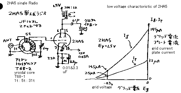
of his heater voltage. See the right side of the figure! This is low voltage
character of 2HA5. Plate current is changed from 2.5uA to 32uA when the
grid voltage changed from -0.3V to 0V. Yes it is controlled. But on the
same tome, the current of grid changes from 14.5uA to 145uA. Yes the current
gain ( same dimension from hfe of transistor ) is 32/145=0.22. It is very
low , is'nt it? And , because the grid requires the current to act, the
input impedance of this valve is also very low. It is 0.3V/145uA= 2 kohm.
*** Therefore I made the radio shown on the left side of the figure. In
this radio , the grid is tapped down on the tune coil, in order to adapt
the low impedance of grid. The total voltage gain of this radio (from ANT
to Phone) was 18dB. It is bigger gain than the "gerumanium radio".
My gerumanium radio has 6dB voltage gain (not power gain!). I compared
to hear this radio with the gerumanium radio. I felt that this radio has
slightly bigger sound than the gerumanium radio.
This radio uses the plate detector. The voltage gain of this radio is culculated
as follows. Gain A = ( 5 /1 ) [ turn of coil] * ( 32-2.5 ) mycro ampere
[ plate current ] / 0.3V [ grid voltage ] * 20k [ load impedance ] = 10
times ( 20dB ).
20dB ( culculated gain ) is near from 18dB ( measured gain ).
Except you have very soft brain, you can not understand this page. In this
page I deal the tube as a current amplifying material. Because I make such
a tricky experiment , I am called as tricker
2ha5.gif

2HA5単球1.5ボルトラジオ
このページの冒頭に,このページの作品は実用ではありませんと、お断りしておかねばならないでしょう。これまで、低い電圧での真空管の利用についていくつ
かの実験的な作品を紹介してきましたが、「真空管を最も低い電源電圧で使用する事に挑戦しよう!」という共通の主題の元に作ってきました。今回の作品もま
た,この主題に関する結果の1つです。私は,真空管を100種類ほど持っています。それらのほとんど全ては,私と私の弟が約25
年前に廃棄されているテレビセットから拾い集めてきたものです。これらの手持ちの真空管に対して、プレート電圧が何ボルトから電流が流れ始めるかを試験し
ました。その実験の結果は2HA5という名も無いというか有名でない真空管が,優勝者だったわけで。また、この三極管の格子は,プレート電圧1.5Vボル
トの動作でも、プレート電流をコントロールすることができることがわかりました.この真空管のヒーターの設計値は,2.4V-0.6Aです。また、この真
空管は,カラーテレビセットのチューナーに使われていた物です。多分,この真空管は,日本のオリジナルだろうと思っています(元設計がGEやRCAでは無
いという意味)。そして,私は,実験の結果、この真空管が,ヒーター電圧も1.5Vでも動作することができるということに気づきました。図の右側を見て下
さい!
これは,2HA5の低電圧特性です。格子ボルト数が,−0.3から0Vに変わったときに,そのプレート電流は,2.5uAから32uA
に変わりました。それは,すなわち,コントロールされています。しかし,それと同時にで,格子の電流は,14.5uAから145uA
に変わります。そしてつまり,格子が,動作する為にそれ自体電流を要求するので,この真空管のグリッドの入力インピーダンスは,またとても低いという事に
なります。格子の入力インピーダンスを計算すると,0.3V/145uA=
2 kohm
です.つまり、制御グリッドが電流を必要とするので、この場合普通の真空管の様に電圧制御素子として扱うのはふさわしくありません。電流利得(
トランジスターのhfe と同じ単位) は,すなわち32/145 = 0.22です。それは,とても低いでしょう。***
それで,ラジオを図の左側で示した様に作りました.このラジオでは,格子の低い入力インピーダンスに適応させるために,格子は同調コイルにタップダウンで
リンクさせています.このラジオ(アンテナからホーンの間
) の総計の電圧利得は,実測18dB
でした.それは,「ゲルマニウムラジオ」よりより大きいゲインです。私のゲルマニウムラジオは,6dBの電圧利得を持っています(
パワーゲインじゃ有りません! この場合は総合電圧利得です。)
ゲルマニウムラジオとこのラジオを聞きくらべしてみました。このラジオは、ゲルマニウムラジオよりわずかに,より大きな音で聞こえました.
それからこのラジオはプレート検波をしています。検波効率が100%と仮定した場合の、総合電圧利得は計算上、下記の様になります。利得A=5「コイルの
巻き数比」*{(32ー2.5)マイクロ「プレート電流の変化」/0.3「グリッド電圧の変化」}*20K「負荷インピーダンス」=10倍、よって
20dB。これは実測値18dBと良くあっています。
そうとう頭の柔らかい人じゃないと以上の解説は理解出来ないでしょう。なにしろ真空管を電流増幅素子として扱っているんですから。こんな事やってるから「砂村さんのインチキ作品」なんて言われちゃうんだなあ。はいはい。
back to index

