Two types of 2 transistor 7MHz radio
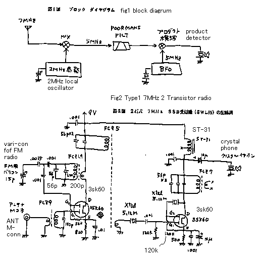
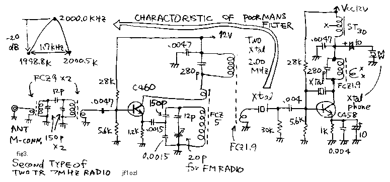
I will show you two types of 7MHz radio. See fig1! Both types are single conversion super heterodyne. ** See fig2! Gate2 and drain of first transistor makes an oscillator. Antenna signal is injected for gate1. Therefore this transistor works as a convertor. 5MHz IF signal passes through a crystal filter made by a crystal. This simple filter is called a "poor mans filter". Gate2 of second transistor makes a crystal oscillator. And IF is poured on the G1 of this transistor. Therefore this circuit works as a product detector. The audio beat signal between the 5MHz oscillator and the IF signal is heard. ** See fig3! In this case the diagram is the same as upside. But only IF frequency was changed for 2MHz. Convertor of this radio is the same circuit from the convertor of normal 6 transistor AM radio. Filter is also the poor mans filter. Crystal between collector and gate oscillates 2000.6 KHz beat. Therefore this circuit acts as a product detector while a IF signal came from the base. ** I could hear the domestic SSB and CW QSO of 7MHz with the dipole antenna in my house. I think these circuits are the best for the new homebrewer.

2石式7MHz受信機2題
2種類の7MHz ラジオをお見せしましょう.両方とも,シングルコンバージョンスーパーテロダインです.** fig1 を見て下さい!! 最初の トランジスターの第2ゲートとドレインは,オシレーターを形成しています.一方空中線信号は,ゲート1に注入されています.それゆえに,このヂュアルゲー トFETトランジスターは,周波数変換器として働きます.5MHz IF 信号は,水晶フィルターを通過します.この簡単なフィルターは,「貧乏人フィルター」と呼ばれています.第2のトランジスターの第2ゲート は,水晶発振器を形成しています.そして,一方、中間周波信号は,このトランジスターの第一ゲートに注がれています.それで,この回路は,プロダクト検波 器として動作しています.5MHz局発信号と,IF信号の間の差の周波数がオーディオの信号として,聞こえます.** fig2 を見て下さい!! この場合,ダイヤグラムは,上の図と同じです.しかし中間周波数は2MHzになっています.このラジオの周波数変換器は,普通の6石式トランジスターラジ オの周波数変換機と同じ回路です.フィルターは,これもまた「貧乏人フィルター」です.コレクターとゲートの間の水晶は,2000.6 KHz のビートを発振します.一方,中間周波信号が,ベースに入りますから,この回路は,プロダクト検波器の役をつとめます.**家のダイポール空中線で、国内 のSSB ,およびCWQSO を聞く事ができました.これらのサーキットが,自作家には最もよい試作題材だと思います.


2trrx1.gif


2trrx2.gif


back to index