COLLECTED BY
Organization:
Alexa Crawls
Starting in 1996,
Alexa Internet has been donating their crawl data to the Internet Archive. Flowing in every day, these data are added to the
Wayback Machine after an embargo period.
Starting in 1996,
Alexa Internet has been donating their crawl data to the Internet Archive. Flowing in every day, these data are added to the
Wayback Machine after an embargo period.
TIMESTAMPS
Simple 430 SSB transceiver
1.Circumstances of this product.
I made and used 50MHz-ssb transceiver for these years. One night on the air, my
friend (JE3TXU/1:Mr.Haraguchi) said to me that,"50MHz is easy to build,
and we must challenge to build 430MHz ssb." This is my first
430-SSB-transceiver. This is very simple. This transceiver uses bilateral
theory in many parts of whole configuration.
2. General construction of this transceiver
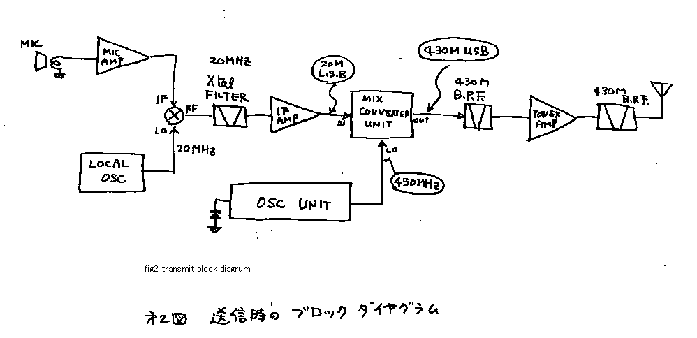
See fig 2! This is a diagram of transmitter. Audio signal is amplified by audio
AMP. It is inserted to IF-port of the DBM. On the other hand local oscillator
makes 19.9961-MHz signal. It is inserted on a local-port of DBM. Then I can
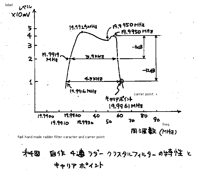
receive 19.9961-DSB signal on the RF-port of DBM. See fig4! Only lower side
band of DSB signal can pass through handmade-crystal filter. Therefore there
comes LSB-signal on the exit of the crystal filter. This signal is amplified by
IF-AMP. And it is inserted to the frequency converter. On the other hand, 14MHz
VXO is constructed with the 42.222MHz named crystal. And it is multiplied 32
times. There comes 450MHz signal. At the converter 450MHz CW-signal and
19.9961MHz-LSB signal are mixed. There comes 430MHz-USB signal and 470MHz-LSB
signal. Only 430MHz signal can passes through the 430MHz band pass filter.
RF-AMP is only single stage. And after the signal passes through the BPF again,
it goes to the antenna, and radiated from the antenna to the air. I will explain
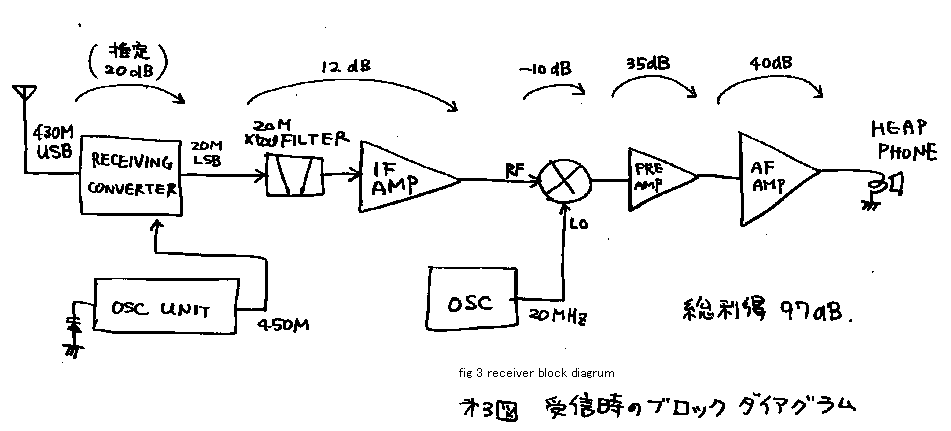
about the receiver. See fig 3! The signal from the antenna passes through all
each the circuits, as the counter direction from that of transmitter. Two
oscillators continue to work in both timing of receive and transmit. Therefore
I have no need to be afraid the changing of the frequency between receiving and
transmitting. Originally, by the way of development, the transmitting-converter
was used also as receive-converter. But the self oscillation has happened.
Therefore I made FET-receive converter another from transmitting-converter. I
can re-construct the transceiver easily, because it is constructed on the
mother-board. The AF-AMP has 40dB-gain. The gain of it is enough to the
microphone-AMP. But for the receiver, I need extra gain. Therefore I sat the
pre-AMP. It gives me more 35dB-gain only while receive.
3. Explanation of each block.
...About local oscillator unit....
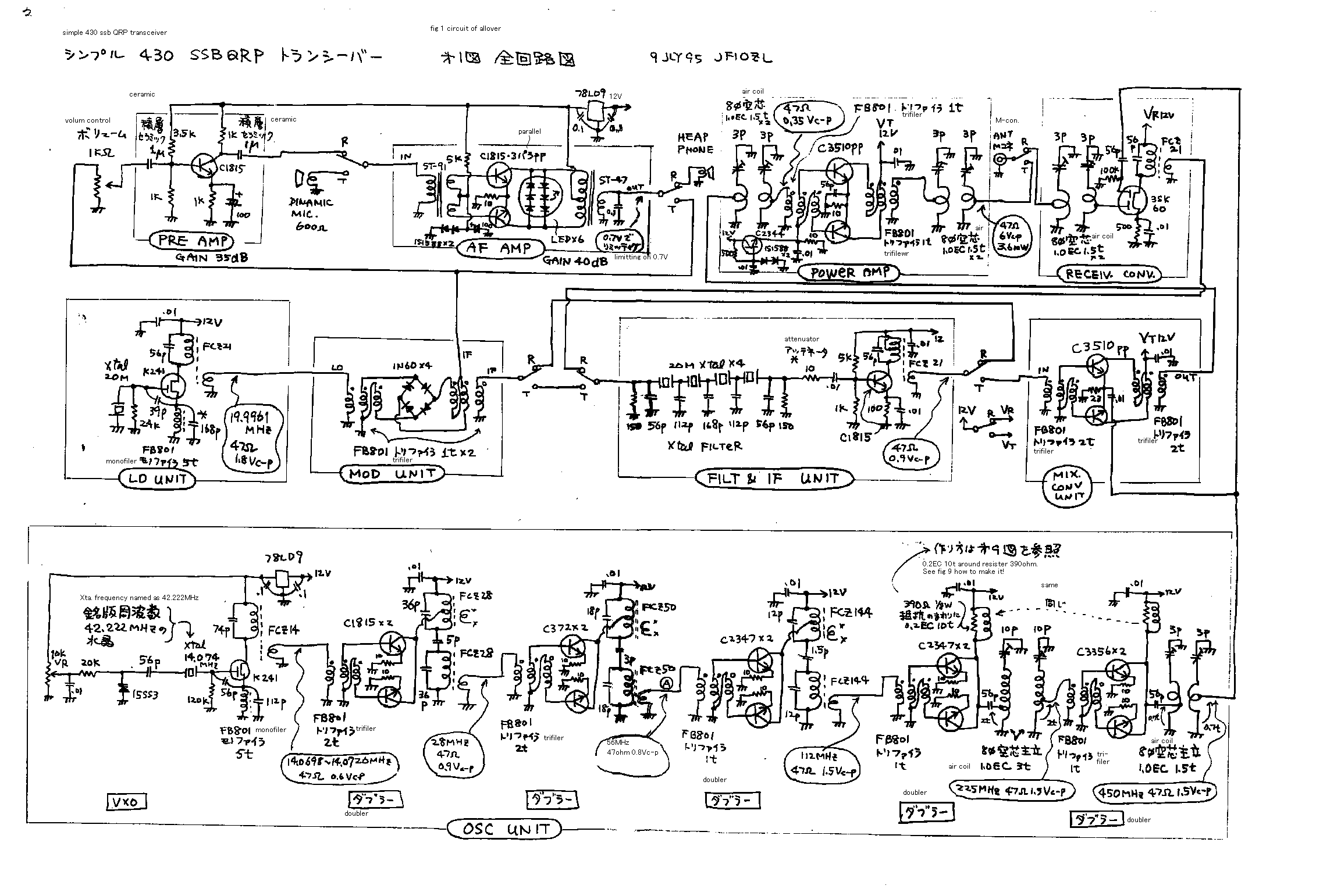
Oscillator is constructed by 14MHz-VXO and five times (doubler=) double
multiplier. See fig 1. VXO is made of Varicap-diode. I like to use a
air-varicon(variable capacitor is called so in Japan).
But in this machine, I use the Varicap-diode. By using Varicap-diode I can lay
out the oscillator-unit and tuning-dial freely in the case. When I use an
air-varicon, I must locate the air-varicon near from the local-oscillator unit.
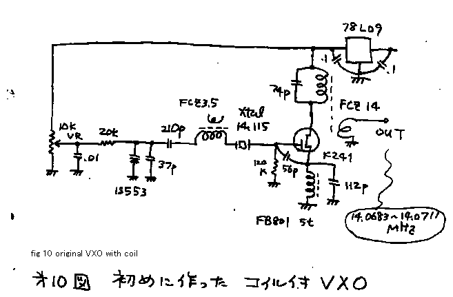
See fig 10! Originally oscillator was constructed by VXO using coil. Some operator
sends me the report that my signal has QRH. Therefore I changed the
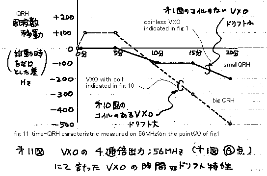
construction. I used the coil-less-VXO. See fig 11! Original-coil-VXO has 600Hz
of QRH by 20 minutes. And the coil-less VXO is improved in this point. By this
VXO transmitting-frequency is tunable from 430.2352 MHz to 430.3256MHz. I
bought the 42.222MHz third overtone crystal by mail-order business and use it
with it*s original frequency. The five-times-doubler is constructed by
push-push doubler. I learn about this doubler in the ARRL-handbook. This type
of doubler can work very sure. Because it works as C class amplifier, it has no
possibility to make useless self oscillation. And this type of doubler can make
very pure signal. Because it has double tuner on the corrector, it avoid to
through the original frequency, it avoid to product three harmonic frequencies.
Yes you can believe it is the double frequency signal if you can get some
signal on the output of this circuit. I do not have a spectrum analyzer, therefore
I must choice such a reliable and easy to tune circuit. I want to say one more
this type of doubler is free from miss tuning. ....Five doublers are
constructed by the same circuit. But the dealing frequency is different from
each other. I must choose the transistor to match the frequency.
The ft-of the transistor must be 10 times bigger than the frequency dealt by
that circuit. Or else you can not get the enough electric output power on the
outside of the any types of amplifier or multiplier. Yes, it is very important
basic theory that you should care about it. Please take a red pencil and please
mark the upper line of your CRT display!
The first doubler makes 28MHz output, so it is made by 2sc1815 (ft=80MHz).
The second doubler makes 56MHz output, so it is made by 2sc372 (ft=200MHz).
The third doubler makes 112MHz output, so it is made by 2sc2347 (ft=650MHz).
The fourth doubler makes 224MHz output, so it is made by 2sc2347 (ft=650MHz).
The fifth doubler makes 460MHz output, so it is made by 2sc3356 (ft=7000MHz).
You say that I do not keep 10 times theory? Yes my friends call me "About
man". HiHi.
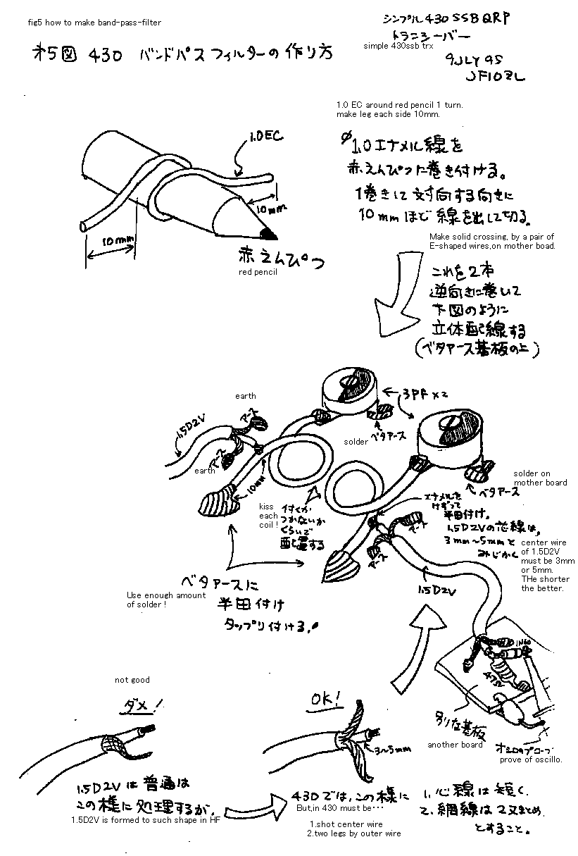
In the UHF circuit, the leg of the parts must be made very short; else you meet
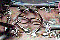
the self-oscillation or lack of output-power. See fig5! It indicates how to
make 430 MHz band-pass-filter. In this filter, if you lay each coil more
closely, you can get more power. But too close lay out gives the poor filtering
character. If you take some space from each other, you can get cleaner signal
from it. But too much distance gives you poor signal strength. Therefore, you
must adjust the combine-factor of this band pass filter. In order to tune the
connection factor, solder the 1.5D2V (Japanese industrial standard calls so) coaxial
cable wire on the coil. And on the other side of the cable, join the dummy load
and 1N60 diode and prove of oscilloscope. If you joint the dummy-load and prove
directly on the side of the band-pass-filter-coil, the electro-magnetic force
of 430MHz makes the influence to the prove of oscilloscope and you can not
measure correctly.
.....Audio frequency amplifier....
Audio-frequency-amplifier is constructed by a normal
transducer-push-pull-amplifier. Three-series LED is connected on the first side
of Trans. The LED begin to brink when it*s voltage becomes over 2 volts.
Therefore it can limit the voltage with 2 volts. Therefore this three LED array
limits the voltage amplitude on the first side of the output transformer with
6Vp-p. If you use more LED, limiting point becomes bigger. The LED brinks, while
I speak for my microphone. It indicates this limiter makes its job then.
....Local oscillator unit ...
I must use the five 20MHz crystals to build this gear. Four of them are used
for filter. One of them is used for the local oscillator. See fig4! At first I
made a filter. And I tried some types of oscillator to make suitable 19.9961
MHz signal. FET-COLPITS-oscillator is used for the purpose. You must adjust the
capacitor between source and ground to get the suitable frequency. By this
method you can make SSB-signal with a set of 5 the same crystals.
....modulator unit ...
Modulator unit is made by diode-ring-modulator. You must limit the audio signal
smaller than half (-6dB) of the carrier signal. Else DSB signal becomes dirty.
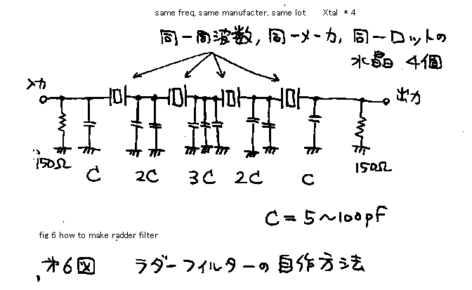
....ladder type crystal filter ...
See fig 6! Join four the same crystals series. And join the nine same
capacitors between the crystals and the ground. The capacitor becomes bigger,
narrower the pass band becomes. But you cannot change the center of pass band.
It is decided by the original frequency of the crystal. Put the attenuator of
resister on the front and end of the filter. Else shape of pass band becomes
bad. This filter has the loss about 10dB. So you must use IF AMP after it, to
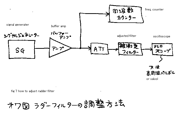
cover the loss of the signal. See fig 7! It indicates how to adjust the filter.
You can plot the characteristic of the filter by this system. If the pass band
is wider than 4 KHz, change the capacitors for bigger one. And try again. If
the band pass is narrower than 2.5 KHz, change the capacitors to smaller one.
It may need 6 hours to make this adjustment with this signal oscillator and
frequency counter.
If the filter is narrower than 2 KHz your transmitting-voice may become like
nose-closed-person, because the upper half of your voice be cut. If the filter
is wider than 5 KHz, your rig may have QRM on the crowded band, because the
filter can pass the neighbor side signal. Therefore the pass band of the filter
should be adjusted between 2.5 to 4 KHz.
...IF AMP ....
Next stage is IF AMP. If you can complete these units, please test it! Contact
the vinyl wire on the output of IF AMP! Make loose contact between the wire and
some kind of radio. The radio must be wide band type to receive the IF
frequency 20MHz in this case. The radio must have BFO (beet-frequency-oscillator)
on it to demodulate the SSB signal. If you can get some helper, put the
microphone of the transmitter in front of the mouth of your helper! If you can
not get any helper, please use the tape recorder. Adjust the carrier-point! If
the carrier is located too far from the band-pass of the filter, you cannot
hear some low voice clearly like the Buuuu or wooooo, because the lower
spectrum of the voice is cut. If the carrier is located too near from the
band-pass of the filter, you cannot hear the high voice like sha syu syo.
.... Converter....
Converter is constructed by the push-pull-active-single-balanced-mixer. Also in
the case of this mixer, the IF signal must be smaller (lower signal strength
level) than the local signal. Therefore I put the 10-ohm-resister in front of
the IF AMP. In stead of this tuning, you can add one more amplifier on the
local oscillator. It is a matter of total signal revel planning as the
transmitter. ............I will explain about the tuning of emitter resister of
the converter. The smaller resister if you use, the conversion-gain becomes
bigger. But it may need more power as the local signal. The bigger resister if it
may be used, the smaller level of the oscillator could be able to drive this
converter satisfactory. But the conversion gain becomes small in this case. In
this machine I made, the conversion gain becomes -8dB. Its loss is smaller than
diode converter. But the conversion gain is far smaller than the normal narrow
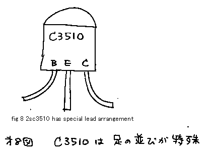
band converter. In this converter you must use high ft-transistor. I use 2sc3510
(ft=3500MHz). See fig 8. Emitter-base-collector is printed on the package of
this transistor. I guess the designer of this transistor (Technika of Hitachi)
may be kind person. HiHi
... power AMP....
Power AMP is constructed by the wide-band-push-pull-A-class AMP. This amplifier
product very clean signal. But ft of the transistor must be bigger than ten
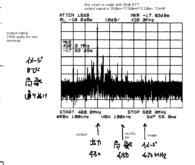
times of 430MHz. Output-power of AMP is 10mW QRPP. Please look the last figure
of this page. I measured the total transmitting signal frequency character with
spectrum analyzer of Japanese amateur radio association. The through of local
signal 350MHz , and the difference side of the converter 470MHz is suppressed
40dB or more than the transmitting signal of 430MHz.
....Receiver ...
In the receiver, all the circuit is used as the counter direction from the
transmitter. All the circuits are changed by small relay. Only the front
converter of the receiver is constructed by two gates FET. It is normal usage
of this FET that is developed to use the front converter of TV receiver set.
....4.... When I use this transceiver.....
I make some local-expedition, on the hill, about 500 meters high, on the Tsukuba Mountain. With
10 elements Yagi-antenna, I could make QSO with the stations on Yokohama and Tokyo. I got 51 to 57 reports. MY rig is 10 mill watts QRPP, but I can use many
elements- Yagi in this band easy. 10mW operation with 10dB gained antenna
has the same meaning with 100mW dipole operation. Let's challenge 430MHz!
Don’t care to make mistake!
At the end of this page ,I will show you the character of the transistors
to help your own choice.
2SC1815: Maker= Toshiba: usage Low frequency amplifier general use: Vcbo=60V:
IcMAX=150mA: PcMAX=400mW: hfe=70 to700: fT=80MHz
2SC3510: Maker= Hitachi: usage UHF ,VHF amplifier: Vcbo=20V: IcMAX=50mA:
PcMAX=600mW: hfe=30 to200: fT=3500MHz: Typical 10.5dB on 900MHz
2SK241: Maker= Toshiba: usage= FM VHF Radio frequency amplifier: Mos N
channel: VMAX=20V: Idss=10mA: gm=10mSmax: Cis=3pF: Crs=0.035pF: Power gain
28dB typical on 100MHz
3SK60: Maker= Hitachi: usage= VHF Radio frequency AMP: Mos : VMAX=15V:
Idss=12mAmax: gm=16mS typical: Cis=5pFmax: Crs=0.015pF: Power gain 24dB
typical on 200MHz
2SC2344: Maker= Sanyo: usage High voltage switching ,low frequency amplifier
: Vcbo=180V: IcMAX=1.5A: PcMAX=25W: hfe=60 to200: fT=100MHz
2SC372: Maker= Toshiba: usage =LF/HF amplifier specially designed to use
IF of MW radio: Vcbo=35V: IcMAX=100mA: PcMAX=200mW: hfe=70 to 240 : fT=200MHz
2SC2347: Maker= Toshiba: usage =UHF oscillator ,VHF mixer: Vcbo=30V: IcMAX=50mA:
PcMAX=250mW: hfe=20min: fT=650MHz: Cob=1.5pF
2SC3356: Maker= NEC: usage =HF low noise amplifier: Vcbo=20V: IcMAX=100mA:
PcMAX=200mW: hfe=50 to300: fT=7000MHz: Typical Noise figure=2dB on 1000MHz
簡単な430 SSB トランシーバー
1. この作品の行きさつ
ここ数年間50MhzのSSB トランシーバーを自作して,運用して来ました。ある晩、お空で,私の友人であるJE3TXU/1:原口さんからこう言われました。「50MHz
トランシーバーは,簡単に出来るから,430MHzSSBを作ってみよう。」
そういう単純に技術的チャレンジとして製作した最初の430SSBトランシーバーです。とてもシンプルです。このトランシーバーは,多くの部分でバイラテラル(双方向)原理を使っています。
2. このトランシーバーの.基本構造...
図2
をご覧下さい。送信機のダイヤグラムです。左から説明します。音声信号は,オーディオアンプによって増幅されDBMのIFポートに印加されます。その一方
で,ローカルオシレーターにより,19.9961MHzの信号を作りDBM
のローカルポートに印加します。その時,19.9961MHZのDSB信号を、DBMの高周波ポートから取り出すことができます。図4をご覧下さい!
DSB信号の低い周波数の片サイドバンドは,手製の水晶のフィルターを通り抜けることができます。それで,水晶フィルターの出口にはLSB信号が出て来ま
す。この信号を,IFアンプによって増幅します。そして,それを,周波数変換器に印加します。その一方で,名版周波数42.222MHzの3倍オーバー
トーン水晶を基本波発振させ,14MHzVXOを組んでおきます。そして,それを,32倍に逓倍します。そこには,450MHz信号が出て来ます。周波数
変換器で,450MHz信号と,19.9961MHzLSB信号を,混ぜます。そこには,430MHzUSB信号,および470MHzLSB信号が出て来
ます。そのシグナルのうち430MHzだけを,430MHzのバンドパスフィルターを通り抜けさせます。高周波アンプは,たった一段です。そして,信号
が,またBPFを通り抜けた後に,アンテナに行き空中に放射されます。
次に,受信機について説明します。図3
をご覧下さい。空中線からの信号は、送信機の時とは反対の方向に,回路を通り抜けます。二つの発振器は,受信,送信のどちらの時も同じ負荷で働かせていま
す。ですから受信及び送信時の切り替えに伴い、周波数が変動する心配がありません。じつをいうと、最初の回路では,送信時の周波数変換器と同じ回路を受信
時の周波数変換にも使っていました。しかし,受信時にセルフ発振が,起こってしまいました。それで,FETで受信用専用の周波数変換器を作る事にしまし
た。回路を,マザーボード上で作るので,この様な回路変更が簡単にできます。話は変わりますが、低周波増幅器は,40dBの利得があります。その利得は,
マイクアンプとしては十分です。しかし、受信機としては,もっと利得が必要でした。それで,35dBの利得の低周波プリアンプを増設し、受信時だけ動作す
る様にしました。
3. それぞれのブロックの説明...
....ローカルなオシレーターユニット....
オシレーターは,14MHzのVXO
によって話が始まります。そして,5段のダブラーが続きます。図1.のVXOが,バリキャップダイオードによって作られている事を確認して下さい。私は,
エアバリコンを使うのも好きですが,本機では,バリキャップダイオードによってチューニングすることで,オシレーターユニットとチューニングダイアルを
ケース内で自由にレイアウトすることができたのです。エアバリコンを使うときには,エアバリコンの位置をローカルオシレーターユニットから近くに定めなく
てはいけませんので、その分制約となります。
最初は,VXO発振器は,図10の如くVXOコイル(線輪)付きで作っていました。しかし、交信相手から,QRHのレポートをもらったので,図1の如き線
輪なしのVXOに組み替えました。図11に周波数変動の比較を示します。(ただ、変えたらなおった、よかったよかったで終わらせず、ちゃんとデータを取っ
ておくのが科学者です。)オリジナルのコイル付きVXO
は,20分で600Hz のQRHがあります。一方,コイルなしのVXO
は,この点だいぶ改良されています。このVXOの出力周波数は430.2352メガヘルツから430.3256MHzです。私は,通信販売で
42.222MHz
水晶を買いました。その次の5回のダブラーは,全てプゥシュプゥシュダブラーによって構成されていれます。私は,ARRLのハンドブックでこのダブラーを
知りました。この型のダブラーは,C級で動作しているので、自励振を起こす心配が無く、とても安定に働きます。また,この型のダブラーは,段間の共振器が
2段になっているせいで、2倍で設計すれば必ず2倍しか出てこず、余計な3倍や4倍の出力を出す心配がありませんし、基本波の通り抜けもありません。とて
も純粋な信号を作りだすことができます。私は,スペクトラムアナライザーを持っていませんので,そのような、調整間違いの無い、信頼できる回路をを選択し
なくてはならない訳です。5個のダブラーは,全て同じ回路で構成されています。しかし,当たり前ですが取り扱い周波数は,それぞれ違います。それぞれの周
波数をうまく扱うために,トランジスターを選定する必要があります。
基本的に言って、そのトランジスターのftは,取り扱い周波数より10
倍程度、最低でも5倍は、大きくなければいけません。そうでないと思うように出力が電気エネルギーとして出て来ないで、トランジスター内部で熱に変わって
しまいます。これは一般原則です。最初のダブラーは,28MHzを出力させます。したがって,ここは,安価な2SC1815
( ft = 80MHz )で十分です。第2のダブラーは,56MHzを出力します。したがって,ここは,2SC372
( ft = 200MHz )を使いました。 第3のダブラーは,112MHzを出力します。したがって,ここは,2SC2347
( ft = 650MHz ) によって作りました。第4のダブラーは,224MHzをアウトプットします,したがって,ここも,2SC2347
( ft = 650MHz )でなんとかなりました。第5のダブラーは,460MHzを出力します。したがって,ここは,2SC3356
( ft = 7000MHz ) を使っています。
極超短波では部品の足を短く切って,作らなくてはいけません。でないと,部品の足の線すなわちリードで高周波が減衰して出力パワーが思うように出てこな
かったり、リードが共振して余計な自己発振が起ってしまいます。図5をご覧下さい。430メガヘルツバンドパスフィルターを作る方法を示しています。この
フィルターでは,となりあった、それぞれの線輪を近くにすると,伝達損失が減って、より多くのパワーを出力することができますが、近付けすぎるとフィル
ターの性能が低下して、余計な電波も通してしまいます。お互いの間を少し開けると,フィルターからきれいなシグナルを通過させることができます。そういう
訳で,バンドパスフィルターの結合係数を調節しなくてはいけません。これを調整するために,図5のように,コイルに1.5D2V電線をはんだづけし、その
向こう側に,ダミーロードをつないで、ゲルマニウムダイオードで検波し,オシロスコープで観察します。もし,直接にバンドパスフィルターのコイルにダミー
ロードをつないで,計ろうとすると、430MHzの電磁力が,オシロスコープのプローブに直接に影響してしまい、正しく計れません.
.... 低周波増幅器....
オーディオ増幅器は,普通のトランス式プシュプル増幅器です。LEDが,3個直列でトランスの1次側につながっています。LEDは1個あたり1V以上にな
ると急に多くの電流をながして光だしインピーダンスが低くなるので、これを利用して、3個直列ですので,トランスの一次側の両端の電圧振幅はピークで6ボ
ルト、つまり6V
p - p に制限されます。マイクに向かって大声で話すと、LEDが光り,リミッターが働いていることが解ります。
.... ローカル発振ユニット...
ここでは,5個の 20MHz 水晶を使う必要があります。そのうち、4
個はフィルター用に使われます。残りの1つは,ローカルオシレーターで使われます。図4をご覧下さい。私は,まず始めに、フィルターを作り、特性を計りま
した。そして,このフィルターとの組み合わせでLSB信号を作る為に適切な周波数である19.9961メガヘルツシグナルを得るために,いろいろな発振器
を試みてみました。FETを使用したコルピッツ発振器が,同じ水晶でフィルターの通過帯域上端を発振してくれます。この回路で、適当な周波数を得るために
は,ソースと接地の間のコンデンサーを調節する必要があります。この方法によれば,SSB(LSB)信号を5個の同じ水晶さえあれば、作ることができま
す。
.... モジュレーターユニット...
モジュレーターユニットは,リングダイオードモジュレーターで構成されています。この回路では、音声変調信号(オーディオシグナル)は搬送波振幅の半分以下に制限してやらないと、発生したDSB
シグナルが,汚くなり、交信相手から汚い音だといわれてしまいます。
.... はしご型水晶フィルター...
図6 をご覧下さい。 4個の
同じ水晶を直列につなぎます。そして,水晶と接地の間に図のように9個の同じコンデンサーをつなぎます。コンデンサーが,大きいほど,パスバンドが狭くな
ります。しかし,パスバンドの中央の周波数を変えることはできません。それは水晶の本来の共振周波数によって決まってしまいます。(本当は周波数下端固定
だそうだが、私の経験的には中央固定くらいが実感)。フィルタのフロント,およびフィルターの終わりの部分に抵抗のアッテネーターを置いて下さい。でない
とパスバンドの形が,悪くなります。このフィルターには,10dBのロスがありますので,その後にIFアンプを使い損失を取り戻さなくてはいけません。図
7
をご覧下さい。フィルターの調節方法を示しています。このシステムにで、フィルターの特性を把握できます。測定した結果、もしパスバンドが,たとえば
4KHzより広ければ,より大きいコンデンサーを使って作りな直さなくてはいけません。そして,また、もう一度測定してみて下さい。もしバンドパス
が,2KHzより狭ければ,より小さいコンデンサーを使って再度挑戦が必要です。図7の様なシグナルジェネレーターと周波数カウンターを使った調整には,
希望の特性を得る為に、調整時間として6時間程度が必要と覚悟ください。もしフィルターが,2KHz
より狭いまま送信したとすると、送信時の声は鼻がつまった様に聞こえます。もしフィルターが,5KHz
より広ければ,あなたのリグは,隣の周波数まで復調しようとするので、受信時に混信しやすくなります。まあ、混んでさえいなければ害は大きくありません
が。。。そういった訳で,フィルターのパスバンドは,4KHzと2.5KHzの間で調節されなくてはいけません。メーカーのリグの様にぴったり
2.5kHzが理想ですが、少し広めの方が、狭めよりはましです。
... IF アンプ....
ラダーフィルターの後はIF アンプです。もしここまで、ユニットが完成したら,ここまでで仮の送信テストをして下さい。IF
アンプの出力にビニール電線を付けて下さい。
電線とラジオの間は緩く結合するようにします。ラジオは,広帯域受信機が必要です。またラジオは,BFO(ビート周波数オシレーター)
を持ってる物でなくてはなりません。子供さんにでも送信機のマイクからしゃべってもらうか、テープレコーダーから音声をいれる等してヘッドホンでモニター
しましょう。そして、キャリアー周波数を調節して下さい。もしキャリアーが,フィルターのバンドパスから遠過ぎる位置ならば,低音がうまく電波に乗らない
ので,ブーとかウーとか言う声かうまく聞けない現象がおきます。逆に、もしキャリアーが,フィルターのバンドパスから近すぎるかパスバンドに入り込んでし
まっていると,今度は高音が伝わらなくなるので、シャシュショといった撥音がうまく伝わらなくなります。
.... 周波数変換器....
周波数変換器は,プッシュプルアクティブシングルバランスドミキサーによって構成されています。このミキサーの場合もまた,IF信号はローカルシグナルよ
り低いレベルでなければいけません。逆にいうと、
IF信号よりも十分強力なローカル信号が必要です。それで,私は,10オームの抵抗をIF
アンプのフロントに入れて調整しています。逆にオッシレータをもう一段増幅しても良いのですが、ここでは,信号レベルを減衰させる方法をとりました。この
辺は、送信機全体での信号レベルの配分の問題です。次に,この形式の変換器のエミッター抵抗の影響について説明しましょう。抵抗をより小さくすると,信号
伝達器としての転換ゲインが,大きくなりますが、その分、エミッタ抵抗を駆動するオシレーターからの注入電力レベルは、より大きなレベルが必要とされま
す。こ逆に、エミッタ抵抗を大きくすると,信号伝達器としての転換ゲインが,小さくなりますが、その分、オシレーターからの注入電力レベルは、より小さい
レベルで間に合う様になりオッシレータの設計が楽になります。このへんも全体のレベル配分において考慮が必要ですしまた調節が可能です。私の作った定数で
の転換ゲインは-8dB
になりました。ダイオード変換器の変換損失よりはやや少ない変換損失です。ただし、入出力に共振機をもった、一般の能動型周波数変換機の様に、変換利得が
出るまでは行きませんでした。この変換器は広帯域で動作させるので,ftの高いトランジスターを使う必要があります。私は,2sc3510
( ft = 3500MHz) を使いました。このトランジスターは、図8のように. エミッター-
ベース-
コレクターがトランジスターのパッケージに印刷されています。普通のトランジスターとは異なる配列なので、わざわざ印刷したのでしょうが、このトランジス
ターの設計者(日立の人)は,きっと親切な人だろうと思います。はいはい。
... パワーアンプ....
パワーアンプは,広帯域プシュプルの構成で入力信号よりも大きなバイアスを流していますので、Aクラス動作です。この型のアンプは,オーディオ増幅器とし
ても、最も贅沢な形式として知られていますが、とてもきれいな信号を送ります。しかし,トランジスターのftは,送信電波の430MHzに対して10倍程
度なければ、うまく増幅できません。このアンプの出力電力は,10mWとQRPP
です。何年か前、多分1997年頃に、ハムフェアの計測コーナーで測定してもらった結果を、一番下におみせします。キャリアーの450MHzや逆ヘテロダ
イン470MHzの通り抜けが心配でしたが、40dB以上押さえられているので、まあまあでした。
.... 受信機...
受信機では,信号は回路の中を,送信時とは反対の順番で流れてゆきます。すべての回路は小さいリレーによって切り換えます。ただ,受信機の前面の変換器(フロントコンバーター)だけは,ヂュアルゲートFETによって受信専用回路が組まれています。この回路は,このFET
の使用方法としては最も標準的な普通の使い方です。
4.このトランシーバーの使用感
筑波山の中腹、高さ約500
メーターの場所(つつじヶ丘)で移動運用をしてみました。10エレメントの空中線で,横浜や東京とQSOができました。51〜57
のレポートをもらいました。(59は無かったですはいはい。)このリグは,たった10mWですが,このバンドでは多エレメントの八木を使うことができま
す。10dBの利得の空中線を使った10mW運用は,ダイポールアンテナを使った100mW運用に相当します。430MHzに挑戦しましょう。失敗を恐れ
ずに!
最後に、トランジスターを選定する時の参考に、私の使ったトランジスターの特性を示します。申し訳ありませんが、だぶるので、英語の説明のおしまいをご覧ください。
430ssb1.gif
430ssb2.gif
430ssb3.gif
430ssb4.gif
430ssb5.gif
430ssb6.gif
430ssb7.gif
430ssb8.gif
430ssb9.gif
430ssb10.gif
430ssb11.gif
430ssb12.gif
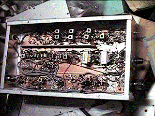
430ssbph11.gif...View of whole this transceiver without top cover
430ssbph22k.gif...View of 430 band pass filter
back to index


