COLLECTED BY
Organization:
Internet Archive
The Internet Archive discovers and captures web pages through many different web crawls.
At any given time several distinct crawls are running, some for months, and some every day or longer.
View the web archive through the
Wayback Machine.
Web wide crawl number 16
The seed list for
Wide00016 was made from the join of the top 1 million domains from CISCO
and the top 1 million domains from Alexa.
TIMESTAMPS
7MHz 3Transistor 4W CW transmitter
7m3trpf.gif
 I
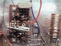
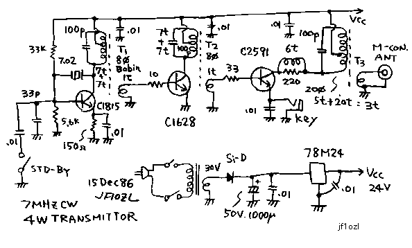
will show you my first full handmade transmitter. This is three stage CW
transmitter for 7MHz. I ordered the crystal for the crystal's maker. It
cost 12 dollars. The signal made by the oscillator is amplified by the
two stage C class amplifier. Power supply voltage is 24V. This voltage
was chosen in order to make strong signal. A piece of alumimum is put on
the collector of the driver transistor. The final transistor is put on
the case for the heat sink. Resistors on the base (10 and 33 ohms) is used
to stop the self oscillation. The small coil on the collector of the final
is also oscillation stopper. This coil is winded around the resistor for
5 turns. Stand by switch stops the osccilation. But on this timing , the
Bias current is not stopped. This reduces the drift of the frequency. It
is better than the system to stop all current on the transmitter. When
I used this transmitter, I had no need to care about TVI. But, I will have
to use the low pass filter between this transmitter and the antenna now.
I made 50 domestic QSO with this transmitter and the SWL radio. Before
complete this gear, some self oscillation happened, some transistor was
broken, somebody send me a report that I had bad tone. Therefore I has
very happy , when I made first QSO with this machine. Please make such
a simple transmitter on your first projects! Not to make all band transceiver!
I will show you the spec of the transistor.
I
will show you my first full handmade transmitter. This is three stage CW
transmitter for 7MHz. I ordered the crystal for the crystal's maker. It
cost 12 dollars. The signal made by the oscillator is amplified by the
two stage C class amplifier. Power supply voltage is 24V. This voltage
was chosen in order to make strong signal. A piece of alumimum is put on
the collector of the driver transistor. The final transistor is put on
the case for the heat sink. Resistors on the base (10 and 33 ohms) is used
to stop the self oscillation. The small coil on the collector of the final
is also oscillation stopper. This coil is winded around the resistor for
5 turns. Stand by switch stops the osccilation. But on this timing , the
Bias current is not stopped. This reduces the drift of the frequency. It
is better than the system to stop all current on the transmitter. When
I used this transmitter, I had no need to care about TVI. But, I will have
to use the low pass filter between this transmitter and the antenna now.
I made 50 domestic QSO with this transmitter and the SWL radio. Before
complete this gear, some self oscillation happened, some transistor was
broken, somebody send me a report that I had bad tone. Therefore I has
very happy , when I made first QSO with this machine. Please make such
a simple transmitter on your first projects! Not to make all band transceiver!
I will show you the spec of the transistor.
2SC1815:Pc=400mW:ft=80MHz:Vcbo=60V:Ic=150mA 2SC1628:Pc=1W:ft=120MHz:Vcbo=180V:Ic=50mA
2SC2591:Pc=20W:ft=250MHz:Vcbo=150V:Ic=1A
PS:About the point of keying In this example keying is made on the final.
You can make keying on the second amp. But if you make the keying on the
second amp, the chyuuing will be happen. Chyuuing is the QRH of tone of
the signal. It is heard by the listener of your signal like " chyuuu
chyu chyuuu ...". On the old handbook of ARRL, the example of CW transmitter
of which the oscillator be keyed was introduced. But such a construction
makes a hard chyuing. In my example, I made keying for final. This makes
a smallest chyuing. But in this case , much current flows on the gaps of
the key. Therefore I must wipes the gaps of the key with a clean paper
once on the day.
7MHz3石式4WCW送信機
私の、初期の作品をもう一つお見せしましょう。固定周波数の水晶発振式3石CW送信機です。水晶は当時CQ誌に広告を出していた、大松さんという水晶メー
カーに注文して、1400円で作ってもらいました。この発振電力をそのまま、エミッター接地のC級増幅で2段増幅して、アンテナに送り込みます。簡単な回
路で大きな出力を得る為に、電源は24ボルトと高めにしてあります。2SC1628には小さなアルミ板を放熱器として、取り付け。ファイナルはアルミの
ケースに取り付けて放熱させています。増幅器の格段のベースの抵抗(10オームと33オーム)は、発振どめです。また、終段のコレクターの所のコイルは、
パラスチック発振止めで、220オーム0.5ワットの抵抗の周りに0.2mmのエナメル線を5回巻いた物です。受信時に完全に発振器のトランジスターの電
流を切ってしまうと、また、送信する時に初期周波数変動があるので、スタンバイスイッチでベースを高周波的に接地して、発振を止め、バイアスは流して置く
様にしています。これでも、再送信時には初期変動があるので、送信始めにはスタンバイスイッチを切ってから、1秒ほど置いて、一呼吸してから、応答
を始め、しかも、いきなり内容にはいらず、必ず応答のはじめは、RRとゆっくり打つ様にしていました。この癖はいまでもぬけません。いまから、見ると、ア
ンテナの前にローパスフィルターを入れたい所です。この当時は共同受信の場所に住んでいたので、この程度はTVIの心配はありませんでした。この送信機
を、別ページの2SK19を使った受信機と組み合わせて、国内約50局とQSOしました。いまから、思い出すと、こんな簡単な送信機でも、発振してしまっ
たり、出力が思う様に出なかったり、トランジスターが破裂してしまったり、いろいろ苦労して作ったので交信できた時は大変うれしかったものでした。皆さん
も送信機を作られるなら、こういった簡単なCW送信機から、初めてください。くれぐれも、いきなりオールバンドのデジタル制御等から取り掛からないでくだ
さい。水晶は、「トラ技」に作ってくれるメーカーさんが何社か広告を出しています。最後に参考までに、各トランジスターの主要スペックを、お伝えします。
2SC1815:Pc=400mW:ft=80MHz:Vcbo=60V:Ic=150mA
2SC1628:Pc=1W:ft=120MHz:Vcbo=180V:Ic=50mA
2SC2591:Pc=20W:ft=250MHz:Vcbo=150V:Ic=1A
追記:キーイングする場所に関してこの例では、最終段をキーイングしています。中間増幅の2SC1628をキーイングするのも良いのですが、若干「チュー
イング」といって、一つの長点を送信する間に周波数が変化して、聞いているほうから、チューチューいって聞こえる現象を招く事になります。さらに、
ARRLの古いハンドブックには、発信段をキーイングする例もありますが、これは「チューイング」が激しく、とても現在では応答してもらえない品質のトー
ンしか発生しませんし、噂によると、発信段をキーイングする構成の送信機はJARDに認可されないそうです。一方、私の紹介した終段をキーイングする方式
は、「チューイング」現象は少なく出来るのですが、キーの接点に流れる電流が大きくなってしまい、接点を時々きれいにしてやらないと、出力が出なかった
り、歯抜け信号になったりしてしまいます。接点に紙を挟んで適当な圧力をかけながら、紙を引き抜くと紙の上に黒い酸化皮膜がはがれて付くので判ります。
7m3tr.gif

back to index

 I
will show you my first full handmade transmitter. This is three stage CW
transmitter for 7MHz. I ordered the crystal for the crystal's maker. It
cost 12 dollars. The signal made by the oscillator is amplified by the
two stage C class amplifier. Power supply voltage is 24V. This voltage
was chosen in order to make strong signal. A piece of alumimum is put on
the collector of the driver transistor. The final transistor is put on
the case for the heat sink. Resistors on the base (10 and 33 ohms) is used
to stop the self oscillation. The small coil on the collector of the final
is also oscillation stopper. This coil is winded around the resistor for
5 turns. Stand by switch stops the osccilation. But on this timing , the
Bias current is not stopped. This reduces the drift of the frequency. It
is better than the system to stop all current on the transmitter. When
I used this transmitter, I had no need to care about TVI. But, I will have
to use the low pass filter between this transmitter and the antenna now.
I made 50 domestic QSO with this transmitter and the SWL radio. Before
complete this gear, some self oscillation happened, some transistor was
broken, somebody send me a report that I had bad tone. Therefore I has
very happy , when I made first QSO with this machine. Please make such
a simple transmitter on your first projects! Not to make all band transceiver!
I will show you the spec of the transistor.
I
will show you my first full handmade transmitter. This is three stage CW
transmitter for 7MHz. I ordered the crystal for the crystal's maker. It
cost 12 dollars. The signal made by the oscillator is amplified by the
two stage C class amplifier. Power supply voltage is 24V. This voltage
was chosen in order to make strong signal. A piece of alumimum is put on
the collector of the driver transistor. The final transistor is put on
the case for the heat sink. Resistors on the base (10 and 33 ohms) is used
to stop the self oscillation. The small coil on the collector of the final
is also oscillation stopper. This coil is winded around the resistor for
5 turns. Stand by switch stops the osccilation. But on this timing , the
Bias current is not stopped. This reduces the drift of the frequency. It
is better than the system to stop all current on the transmitter. When
I used this transmitter, I had no need to care about TVI. But, I will have
to use the low pass filter between this transmitter and the antenna now.
I made 50 domestic QSO with this transmitter and the SWL radio. Before
complete this gear, some self oscillation happened, some transistor was
broken, somebody send me a report that I had bad tone. Therefore I has
very happy , when I made first QSO with this machine. Please make such
a simple transmitter on your first projects! Not to make all band transceiver!
I will show you the spec of the transistor.