COLLECTED BY
Organization:
Alexa Crawls
Starting in 1996,
Alexa Internet has been donating their crawl data to the Internet Archive. Flowing in every day, these data are added to the
Wayback Machine after an embargo period.
Starting in 1996,
Alexa Internet has been donating their crawl data to the Internet Archive. Flowing in every day, these data are added to the
Wayback Machine after an embargo period.
TIMESTAMPS
My original understanding of pure complementary audio power AMP
In my ten age , I understood a circuit of transformer connected push pull
audio power AMP. But in that timing I have read some textbook concerning
about a complementary power AMP. But then I could not understand it. It
describes how it works. But it does not describe how it was developed.
In these days , when I do experiment about a emitter follower, I burst
into understanding of the complementary power AMP. I will show you about
it.
compamp1k.gif

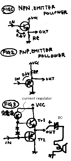
See fig 1 ! It is a emitter follower,the transistor works only to change
the impedance. Output signal is same phase and same voltage span. Input
voltage and output voltage has the relation. That is ( Vout=Vin-0.6 ),
because base voltage and emitter voltage keeps the relation 0.6 volts ,
while it works with correct bias current.
See fig 2 ! It has the same meaning from fig 1. Only it is made by PNP
transistor. In this case , (Vout=Vin+0.6V ).
See fig 3 ! This circuit is only the combined figure of fig 1 and fig 2.
Base of Tr1 is 0.6V higher from the output. Base of Tr2 is 0.6V lower from
the output. Current regulator keeps to excite the twin diode. Therefore
the two bases of transistors are kept for 1.2V. So the transistors works
under correct biased situation in every moment. Vout is 0.6V higher from
Vin. It is the shifted same signal. Output impedance is lower than input.
So it can drive a 8 ohm speaker. While input signal does not exsists, the
power used by this circuit is only small bias current. So it has better
power effet than fig 1.
Because, the "out" point's normal voltage is about a half of
Vcc, you must connect the blocking capacitor between the output and the
speaker. But if you use 5W class " 10cm" speaker, while Vcc is
under 12V, you have no need to use Blocking capacitor, and you can joint
them directry.
compamp2k.gif

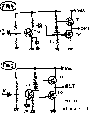
See fig 4! The circuit has pre-AMP before the fig 3. So this circuit has
voltage gain about 30dB.
See fig 5 ! This circuit is developed from fig 4. Pre-AMP and the impedance-exchanger
is connected directry. In this circuit, The Rb of fig 4 is replaced by
the Tr3.
The fig5 is the basic shape of normal pure-complimentary-push-pull-AMP.
Alles rechite gemacht!
ピュアコンプリメンタリーオーディオパワーアンプに関する私の独自の理解.

私は10才代で,トランス式プシュプルオーディオパワーアンプを勉強しました.(当時はそれしかまともに音をだせる回路が無かったのです。)しかし,その
時に,コンプリメンタリーパワーアンプについても本を読みましたが,全く理解できませんでした.それらの本はその回路がどのように,働くかは,述べていま
したが,どのようにそれが,開発されたかは,述べていませんでした.近頃,私が,エミッターフォロアについて実験しているときに,コンプリメンンタリーパ
ワーアンプについて突然わかりました.それについておみせします.
図1 を見て下さい!
それは,エミッターフォロアです,トランジスターは,ただインピーダンスを変えるために,働きます.入力と出力は、同じ位相,および同じ電圧振幅を出力し
ています.この回路では,正しいバイアス電流で働くかぎりは、ベースの電圧と,エミッターの電圧は,0.6ボルトの差の関係を保って変化します。式で書く
と,
Vout = Vin-0.6 です。
図2 を見て下さい! それは,図1 と同じ意味を持っている回路で、PNP トランジスターによって作られた物です.このケースでは,(
Vout = Vin+ 0.6V )です .
図3 を見て下さい! このサーキットは,ただ図1と2の結び合わせられた図です。そして,Tr1
のベースは,出力より0.6V高い電圧です.Tr2
のベースは,出力から0.6V低くなります.電流制御装置によって,双子のダイオードは常に一定電流に駆動されています.それゆえに2個のトランジスター
のベース間は1.2Vに保たれています。したがって,すべての瞬間でトランジスターは正しく動作します.Vout
は,Vinから0.6Vだけいつでも高い電圧です.その入力電圧と出力電圧は,電圧のずれた同じ信号です.アウトプットインピーダンスは,インプットより
低くて,8
オームスピーカーを直接駆動することができます.この回路は,小さいバイアス電流で動作します.したがってそれは,図1よりもよりよい電源電流効率を持っ
ています.
それから、出力端子には、電源電圧の半分の電圧が常時掛かっているので、スピーカと出力端子の間には、直流阻止コンデンサー(BC)を入れる必要がありま
す。しかし、もし、あなたが、12Vの電源電圧で、5Wクラスのスピーカーを使用するならば、そのコンデンサーは、無しでも結構です。

図4 を見て下さい! この回路は,図3. の前にプリアンプを持っています。したがって,この回路は,30dBの電圧利得を持っています.
図5 を見てください! この回路は,図4.から開発されています,そして,プリアンプとインピーダンス変換機は,直接つながれています.このサーキットでは,図4
のRb は,Tr3 によって置き替えられています.図5 は,基礎的な普通のピュアコンプリメンタリープシュ-
プルアンプの形です.
出来上がり!!
back to index


