COLLECTED BY
Organization:
Internet Archive
The Internet Archive discovers and captures web pages through many different web crawls.
At any given time several distinct crawls are running, some for months, and some every day or longer.
View the web archive through the
Wayback Machine.
Web wide crawl number 16
The seed list for
Wide00016 was made from the join of the top 1 million domains from CISCO
and the top 1 million domains from Alexa.
TIMESTAMPS
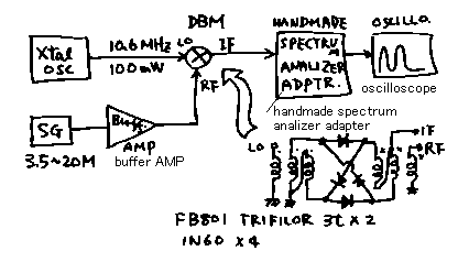
Experiment1.Basic experiment of double balanced mixer as converter mixer
実験1:周波数変換機としてのDBMに関する基礎的実験

DBM (double balanced mixer) is very widely used in our projects. I made
basic experiment of it as a frequency convertor. 10.6MHz CW signal (fRf)
is injected in local port of it. In Rf port, 3.5~20MHz signal (fIf) is
injected. f1=fRf-fIf. f2=fRf+fIf. Changing the frequency of Rf port, I
examined the level of f1 and f2.
fIf=10.6MHz in all time
| fRf |
VRf |
f1 |
Vf1 |
gainf1 |
f2 |
Vf2 |
gainf2 |
| MHz |
mV |
MHz |
mV |
dB |
MHz |
mV |
dB |
| 3.5 |
400 |
7.1 |
200 |
-6 |
14.1 |
200 |
-6 |
| 5.0 |
400 |
5.6 |
200 |
-6 |
15.6 |
200 |
-6 |
| 8.0 |
310 |
2.6 |
130 |
-8 |
18.6 |
130 |
-8 |
| 10 |
170 |
0.6 |
120 |
-3 |
20.6 |
75 |
-7 |
| 15 |
130 |
4.4 |
60 |
-7 |
25.6 |
60 |
-7 |
| 20 |
110 |
9.4 |
60 |
-5 |
30.6 |
60 |
-5 |
I have no need to make some graph. In any time output signal has the signal
loss about 6dB.
Plus frequency signal and minus frequency signal can be obtained in any
frequency.
I tried to change the If and Rf port. But result was the same.
DBM(ダブルバランスドミキサー)は、我々アマチュアにとって良く使う大変汎用性の高い回路です。ここでは、周波数変換機としての周波数の組み合わせと
出力のレベルを調べてみました。ローカルポートに10.6MHzの信号を入れておいて、RFポートにいろいろな周波数をいれて、その二つの周波数の差の周
波数の信号f1と、和の周波数の信号f2を調べたのが上の表です。結果は教科書どうり、いずれの組み合わせにおいても和も差もちゃんと6dB程度のロスで
出力されました。尚、上の図のIFポートとRfポートを入れ替えてもまったく同じ結果でした。
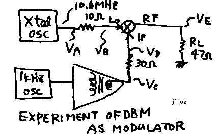
Experiment2.experiment as modulator---- dbmmod1.bmp---signal on Ve point
of the circuit drowing.
実験2:バランストモジュレーターとしての動作

dbmmod.bmp

| Va |
Vb |
Vc |
Vd |
Ve |
Rin(LO) |
Rin(IF) |
Linearity |
| mVc-p |
mVc-p |
mVc-p |
mVc-p |
mVc-p |
ohm |
ohm |
xxx |
| 980 |
750 |
80 |
50 |
50 |
33 |
30 |
good |
| 980 |
750 |
160 |
110 |
100 |
33 |
66 |
good |
| 980 |
750 |
310 |
210 |
200 |
33 |
30 |
good |
| 980 |
750 |
700 |
430 |
400 |
33 |
47 |
good |
| 980 |
750 |
800 |
520 |
500 |
33 |
55 |
slightly crushed |
| 980 |
750 |
1200 |
660 |
600 |
33 |
37 |
crushed |
Rin(LO) = Vb*10ohm / ( Va-Vb)
Rin(IF) = Vd*30ohm / ( Vc-Vd)
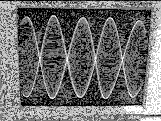
I tryed to make baranced modulater with diode double balanced mixer. I
sorted the 10.6MHz CW local oscillator signal on the LO port of the DBM.
I sorted the 1kHz sign wave audio sugnal on the IF port of the DBM. Then
I could get the double sided signal on the RF port of the DBM. See the
fhoto ! This is DSB signal.
Anyway, input inpedance is about 50 ohms. Audio signal Vd must be smaller
than half of local oscillator signal Vb ,otherwise modulated signal becomes
crushed. Oscillator signal (CW) must be pure sine wave. The four doides
used in DBM must have same characteristics,otherwise output signal is not
good signal. If you make this circuit, you can make experience about how
the signal be distorted on each case.Because you will not be able to obtain
a good signal indicated on this fhoto on first time.
次に、DBMモジュレーターとしての使い方を再測定してみました。ローカルポートに10.6MHzの局発信号を入れておいて、IFポートに1kHZの音声
信号をレベルを変えながら注入してみました。すると、Rfポートには、DSB信号(搬送波抑圧両側帯波)が発生します。写真の様な信号です。とにかく各
ポートのインピーダンスは約50オームでした。低周波信号はローカルポートに印加される高周波信号の約半分以下でないと出力信号が歪んでしまいます。ロー
カルポートの高周波信号はきれいなサインカーブでなければ成りません。さもないと、やはり、出力信号がひずみます。また、DBMに使用するダイオードは特
性のそろった物でなければなりません。さもないと、やはり、出力信号がひずみます。それぞれの場合どう歪むかは、あなたが実際上の図の回路を作ってみて体
験してください。はじめから写真の様なきれいな信号はでてこずに、きっと体験出来るでしょう。
back to index


