COLLECTED BY
Organization:
Alexa Crawls
Starting in 1996,
Alexa Internet has been donating their crawl data to the Internet Archive. Flowing in every day, these data are added to the
Wayback Machine after an embargo period.
Starting in 1996,
Alexa Internet has been donating their crawl data to the Internet Archive. Flowing in every day, these data are added to the
Wayback Machine after an embargo period.
TIMESTAMPS
Transistor curve tracer....trctphk.jpg
 To understand the theory of transistor
amplifier is a basic step to build amateur radio equipment. To understand the
characteristic of transistor is a basic step to understand the transistor
amplifier. Therefore I recommend you to make transistor characteristic in some
way.
You can make the character-curve of a transistor by this system. If you buy it
on a measurement-shop, it needs some thousand dollars. But if you make this
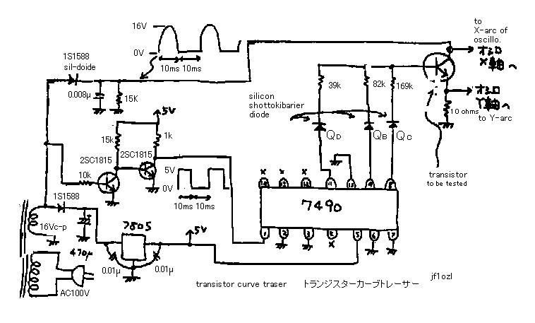
machine, it needs only ten dollars. See fig 1! On the second side of the power
transformer, there comes 20V peak sine signal. IC 7805 makes 5V-DC from it. It
is a power of IC 7490. On the other hand, wave reformer (=made by two 2SC1815)
makes on-off signal. It is clock pulse of IC 7490. On the other hand detector
(made by 1s1588 diode) makes mountain-and-field signal (-~-~-~-~-). It activate
collector of the measured transistor. On the output of 7490, Qb, QC and Qd make
ON-OFF pulses. It changes the base current for 5 stages. See the chart on the
right side of the fig 1. Y-arc (vertical) of the oscilloscope displays the
emitter current of a measured transistor. X-arc (horizontal) of the
oscilloscope indicates the collector voltage. You can see the character of a
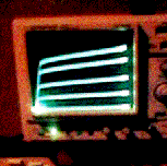
transistor. See the photograph.
トランジスター特性曲線表示装置.
トランジスター増幅器の理論を理解する事は,アマチュア無線機器を作るための基本的ステップとして必要です.その為にはトランジスターの特性を理解することが近道です.ですから,トランジスターの特徴曲線ををなんとかして計るようにすることを勧めます.
普通のオッシロスコープをお持ちならば、このシステムによってトランジスターの特性曲線を作ることができます.それを測定器屋さんでそれを買うには,10
万円以上必要です.しかし,もしあなたが,この機械を作れば,たった千円でOKです.図1
を見て下さい! 電源変圧器の2次側に,20V ピークのサイン波形が出て来ます.IC
7805 は,それから5V-DC を作ります.それは,IC 7490 の電源になります.波形整形器(
2 個の2SC1815 によって作られた ) が,もう一方でオンオフ信号を作ります.それは,IC
7490 の時計脈拍(クロックパルス)になります.1s1588
ダイオードによって作られた検波器が,脈動信号を作ります.それが,被測定トランジスターのコレクターを駆動します.7490
の出力,Qb ,Qc ,およびQd は,ON−OFF
信号を作ります.それは,ベース電流を5段階に変えます.オシロスコープの図1の右側のチャートを見てください。オシロスコープのY軸(縦軸)は被測定ト
ランジスターのエミッター電流を表示します.オシロスコープのX軸(横軸)は,コレクター電圧を示します.こうしてトランジスターの特性曲線を見ることが
できます.上の写真を見て下さい.
7490 timing chart (ベース電流と7490の関係を示すタイミングチャート)
timing -- Qb----Qc---Qd---Ib (uA)ベース電流μアンペア
0-------L-----L-----L---0
1-------H-----L-----L---20
2-------L-----H-----L---40
3-------H-----H-----L---60
4-------L-----L-----H---80
trctnewk.gif

Letter from the reader.I am very grad to receive such aletter. cps means
Hz (cycle per second) HIHI.********
Sure you can use my name it's all right. I also doubled the frequency to
120cps by feeding each end of the TX secondary to the bases of the two
transistors that you used and tying the collectors together and feeding
the output to pin 14 of the 7490.this makes for a better display with less
flicker. The plus step output is fed into pin 2 of the 5741 to get the
set of negative going steps, these go to the double pole double throw slide
switch, the two center contacts of the switch supply one side ,the collector
sweep, the other side center contact the positive or negative steps for
the base of the test transistor.The only catch to this is that you need
a positive and negative relative smooth dc voltage for pin 4 and 7 of the
5741 op amp the plus voltage,i got at the input of the 7805 VR. The negative,used
a diode, and 470uf capacitor tapped off the other end of the tx secondary.
also had to use another diode to make the negative going sweep. didn't
use the 15k or the .005 capacitor for the 120 cps - + sweep. The whole
system works real nice. A power transistor can be pushed to 350ma at 18volts
collector sweep this will heat it up pretty fast. In my original setup
used 2.. 5741's and a 4.. pole double throw switch, the other 5741 is for
the positive going steps amplification. This setup i have on a breadboard
works fine. The original i made a test instrument out of. Sincerly J.S.
----------
> From: [email protected] > To: 'John Sullivan'> Subject: RE:
Curve Tracer > Date: Wednesday, February 04, 1998 7:10 AM > >
Very thanks John to send me your letter. I can understand what you made,
you used A input and A output of the 7490 IC's. But I think it is differcult
to change the polarity of 7490 base current changer. But I want to make
it the homework of this project. I want to introduce your letter on my
honepage , because it will help many reader of my homepage. Please permit
me it. If you permit me , I want to introduce your name with it. I want
your answer. See you.Dear John. de Kaz Sunamura JF1OZL > > ----------
From: John Sullivan > Sent: Wednesday, February 4, 1998 1:07 PM >
To: [email protected] > Subject: Curve Tracer > >
My name is john sullivan and am 67 years old and from Eden Prairie Minnesota
usa. I enjoyed building your curve Tracer very much. Had to run a jumper
from pin 1 of the 7490 to pin 12 and move the input from pin 1 to 14 to
get the fourth step of the output trace. Also used a center tapped 25volt
transformer and a double pole double throw switch and a 741 8 pin OP amp
to get npn and pnp and positive and negative sweep... added a e-b current
select switch and a collector current limit switch to limit current for
different size transistors.Both of these switches are the rotary type.
..have 3 resistors in one and 4 in the other. Thank you very much for putting
your circuits on the internet. You are a very talented person. Sincerly
J.S.
読者からのおたより:ミネソタのジョン
サリバンさんから:氏は、NPNだけでなく、パワートランジスターやPNPトランジスターも計れる様に改造して、製作されたと報告がありました。また氏
は、牽引速度を倍の120Hzにあげて、ちらつきも改善されたそうです。NPNとPNPの切り替えには、2回路のスイッチを使っているそうです。また、氏
は計測されるトランジスターに流す電流に制限をしているそうですが、それでもパワートランジスター計測モードでは、あっという間に熱くなってしまうそうで
す。私の製作例では、水平牽引の周期の半分が0点にとどまっているので、写真を見てお分かりの様に、ゼロ点がすごくあかるいです。ちょっと、オシロがかわ
いそうですが、ここに、両波整流を使うとかえってゼロ点が不明確になってしまうので、こうしてあります。どなたかこれも改善してみてください。オペアンプ
の理想整流回路を使うのが良いでしょうが、まあ、やればやるほど、回路が複雑になってしまいます。
7Mar99. I received the following E-mail
Hi, I built your transistor curve tracer and it works great! I modified
the circuit as follows: 1. instead of the AC transformer, I am using an
audio oscillator to generate the sine wave for the collector circuit. 2.
the audio oscillator has a SYNC ttl output that I use to generate the pulses
for the 7490 chip. These changes allow students to use existing equipment
in the lab. Also, I am testing FET transistors (p channel)...I just reverse
the diode in the collector circuit. Thank You for a great project. Phill,
N1YPS
99年4月7日:読者からのお便り(その2):N1YPSフィリップさんから。このカーブトレーサーをつくりました。良く動作します。私は改造して作りま
した。1.コレクター回路に印加するサイン波を作るのに、専用のオーディオ発振器をつくりました。2.その発振波で7490に同期をかけています。実験室
で生徒に使わせています。(学校の先生らしい)PチャンネルのFETも計れました。との事。
back to index


