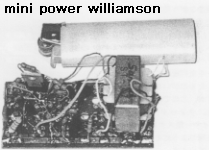
williamsonph.gif
Mini power Williamson Amplifier
When I was about 14 years old, I learned about Williamson amplifier and Ultra Linear amplifier on the radio magazine. Such amplifiers was made by many tubes and Push Pull type transformers. I wanted to make them but I could not buy such a expensive parts.
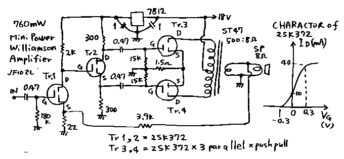
In these days, we can use FET and small transformers. Except of transistor, FET is voltage controlled parts. Therefore we can use FET with the same culculation with tubes. So I made a Dr. Williamson's amplifier with FET's. See the circuit! This circuit is a Dr. Williamson's amplifier in following points.
1. The first voltage amplifier and second signal divider is connected directory with no capacitor.
2. The sources op Push Pull amplifier are used with common source bias resister.
3. The all over negative feed back (7dB) is made from the second winding of the out put transformer to the source of the first stage amplifier.
I used in this gear the special audio FET made by Sanyo company. This FET indicates depression Enhancement characteristics. Therefore this FET can be used with zero bias. The Push Pull stage of this amplifier is zero bias.And work as A class.
The total performance of this amplifier is as follows.
Max power output : 760mW
Voltage amplitude : 40dB
Frequency characteristics : 40dB plus minus 1dB between 50Hz and 33kHz
This performance is enough to be called as HIFI. And this power output is enough to be used on the radio receiver.
If you are the old man and hate to use the transistor, Please try to use the FET with such a old type circuits!
williamson.gif
ミニパワーウイリアムソン増幅器

小さい頃、本でウイリアムソン増幅器やウルトラリニアー増幅器等の、プッシュプル増幅器の記事を読んでよだれをたらしていましたが、拾ってきたラジオの部 品では、こういった高級な回路は実験のしようもありませんでした。なにしろ、真空管は何とかしても、プッシュプル用のトランスが、拾ったジャンクの中には ありませんでしたから。
時は流れて、トランジスター時代になり、さらにFETができました。FETは真空管とおなじに電圧制御素子なので、定数は違えど、真空管の計算式が全て使えます。そこで、真空管と同じ設計思想で、同じ計算式を使って、かの「ウ氏アンプ」を作ってみました。上の回路図です。
どこが、「ウ氏アンプ」なのかというと、
1.初段増幅器と2段めの信号分配機が、直接接続になっています。
2.プッシュプル段のソース同志が、共通接続になっていて、オートバランスです。
3.出力のスピーカー駆動回路から初段のソースにコンデンサー無しで、直接に抵抗結合でトータルな負帰還が掛かっています。(負帰還量は本機では7dB、実測値)
といった、所です。
ここで、使用したFETはサンヨーさんの2SK372で、これは低周波増幅用に作られたものです。特性を実測してみると、いわゆるディプレッションエンハンスメント特性で、ゼロバイアスで使用するとちょうど真空管でいう所のA級増幅になる物です。
本機の総合特性は下記の如く実測されました。
最大出力:760mW
電圧増幅率:40dB
増幅率の周波数特性:40dBプラマイ1dB以内(50Hz〜33kHz)
負帰還量:7dB
十分にハイファイといえる特性です。また760mWの最大出力は普通のラジオ等には十分な電力です。
3.5メガ等で話ていると「開局当時は真空管で自作で開局したが、どうもトランジスターになってからは、壊れやすいとか細かくって作りにくいとか、それ以 上に動作原理を理解し直すのがおっくうで。」等とおっしゃているOMがいらっしゃいますが、ここで示した様にFETは、真空管の回路の置き換えが容易で す。こういうOMの方達はぜひこのアンプの試作を通して、もう一度半田ごてを握っていただきたいとおもいます。

back to index